micro usb wiring diagram
Wiring Diagram Motor Current Setting Below V21. Active 1 year 9 months ago.

Micro Usb Wiring Diagram Micro Auto Wiring Diagram Schematic Usb Electronics Micro Usb
Is there a way of wiring 3 18650 cells to get two simultaneous voltages.

. When powering the Photon from the USB connector make sure to use a quality cable to minimize IR drops current x resistance voltage in the wiring. Usb 2 pinout connections. M12 Connector Coding Pinout Wiring Color Code and Categories Introduction November 28 2019 M12 Connector Coding M12 Connector Pinout M12 Cable Wiring Color Code FLECONN will introduce m12 connector and m12 cable coding pinout wiring color code and installation types for wide readers in designing automation equipments power and signal connection systems.
D8 D9 A8 D10 D16 MOSI D14 RX LED D16 then MISO is at D17 which does not even exist on the Pro Micro. The detail instruction code wiring diagram video tutorial line-by-line code explanation are provided to help you quickly get started with Arduino. D8 A8 D9 A9 D10 A10 D16 MOSI D14 MISO D15 SCLK.
On the other hand the Pro Micro PDF schematic link in this page indicates. HOBOware data logger software must be purchased one license per computer. 8SMC5-USB-B9-2 Two Axis Controller.
A USB cable is included with BHW-PRO-CD and BHW-PRO-USB. The circuit diagram can be seen below. USB Type A Type B Mini-B Micro-B Connectors.
You can connect the 5V output from Arduino to the VCC pin of the MP3 player module. USB-Micro is a fairly recent addition to the USB connector family. Inquire for all others.
Init serial port for DFPlayer Mini softwareSerial. USB Type-C 13 USB 32 and earlier specifications Apple Lightning USB 2 with USB Type-C or USB Standard-A DisplayPort 14 and earlier specifications HDMI 21 and earlier. DCR Accuracy VBus Gnd.
USB Standard-A USB Standard-B USB Micro-B USB Type-C Apple Lightning DisplayPort HDMI. The diagram on the linked page indicates. The tablet version is only compatible with the 5700 Config IO transmitter with the Wi-Fi display option.
Viewed 65k times 9 3 begingroup I make USB cables USB-A to Mini or Micro primarily but dont have any experience with USB-C. There are indeed other power supply methods such as binding posts and benchtop. Wiring diagram for USB-C to USB-A cable.
The maximum settable motor current is 177A RMS 011Ohm sense resistors but the SilentStepSticks can only be used up to 12A RMS. It is 5V tolerant. Windows XP with ServicePack 3 or later is compatible with ProLink III version 43 or earlier iOS and Android tablet version available on iOS and Google Play stores.
Usb 31 pin out. The first USB 30 controller chips were sampled by NEC in May 2009 and the first products using the USB 30 specification arrived in January 2010. The best way to set the motor current is by measuring the voltage on the Vref pin 025V and adjusting the voltage with the potentiometer.
8SMC5-USB Board Circuit Card Wiring Diagram. A Micro SD card An Arduino Uno or Uno compatible board. A D-sub contains two or more parallel rows of pins or sockets usually surrounded by a D-shaped metal shield that provides mechanical support ensures correct orientation and may screen against electromagnetic interferenceD-sub connectors have gender.
8SMC5-USB controllers model lineup. If a high resistance cable ie low current is used peak currents drawn from the Photon when transmitting and receiving will result in voltage sag at the input which may cause a system brown. This 5V33V breadboard power supply includes a micro-USB port and power jack port allowing the taking of direct power from a DC wall wart and outputting it in 5V and 33V regulated voltage.
10 pin usb 2 pinout. Open source software for use with micro-Manager is also available. Hope for your positive and quick reply sir.
See License Agreement for more details. How to make a 9 pin computer power wire a 5 pin. 8SMC5-USB-B8-B9 Three Axis Controller.
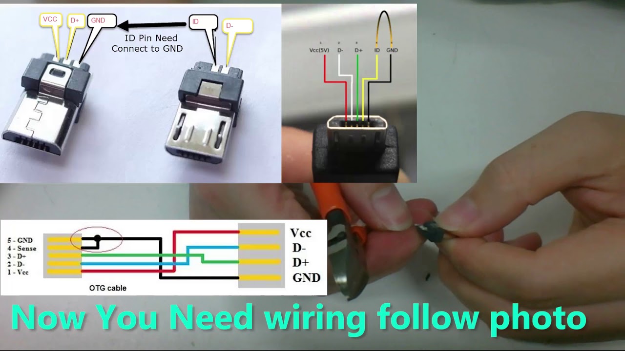
As with USB-Mini the primary concern is size reduction but USB-Micro adds a fifth pin for low-speed signalling allowing it to be used in USB-OTG On-the-go applications where a device may want to operate as either a host or a peripheral depending on. USB 20 4-Pin Type A Type B USB mini Pinouts Specifications. Learn how to use relay with Arduino how relay works how to connect relay to Arduino how to code for relay how to program Arduino step by step.
I would like to create a cable that has a USB-A 20 connector on one end and a USB-C connector on. 8SMC5-USB-B8-1 One Axis Controller. USB 30 connectors are generally backward compatible but include new wiring and full-duplex operation.
I tried using OTG On to Go connector but it is not working in all the device and current rate is also very low. HOBOware Pro is non-refundable upon receipt of software license key. Both are having micro-usb connector at their ends.
Parts with pin contacts are called male connectors or plugs while those with socket contacts are called female connectors or sockets. Ask Question Asked 4 years 3 months ago. Operating System Windows 10 Windows 8 Windows 7 Windows Vista with Service Pack 1 or later.
The written USB 30 specification was released by Intel and its partners in August 2008. Init USB serial port for debugging Serial.
Build Micro Usb Cable Youtube Micro Usb Cable Usb Usb Cable

Micro Usb Pinout Because Everything Is Terrible Diy Electronics Usb Electronics Projects
Pin On Diy For Kids

Usb Aca Cable Otg Usb Nexus 7

Pin En Electronic Shopar Aaesshops Com In 2021 Micro Usb Cable Micro Usb Usb Cable

Usb Cable Extension Different Wire Color Youtube Usb Cable Usb Cable

Recommendations That Can Help You Better Your Own Comprehension Of Computer Tips Computertips Electronics Basics Computer Technology Diy Electronics

How To Make Your Own Motorola Factory Cable In 2021 Electronic Schematics Usb Android Diy

Circuitmix On Instagram Micro Usb Interface With Hdmi Save And Share This Post Tag Your Fr Micro Usb Electronic Schematics Electronic Circuit Projects

How To Make Usb Otg Cable Otg Iphone Cable Apple Charger Cord
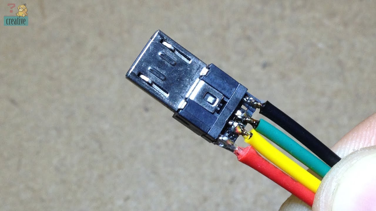
This Video Show You How To Hand Made A Usb Otg For Smartphone This One I Made A Usb Otg Mini Usb To Micro Usb Hoping It S Useful For You Gu

Micro Usb Wiring Diagram Micro Usb Micro Usb Cable Usb

Micro Usb Wire Diagram Copy Usb Wire Diagram Schematic Micro Wiring Cable Power Color Code Otg Usb Micro Usb

Micro Usb Data Cable Pin Out Diagram Others Usb Standards Electronics Lovers Technology We Love Micro Usb Usb Data Cable

4e740826 Micro Usb Otg Pinout How To Make Your Own Usb Otg In 2019 Usb Usb Microphone Electrical Projects Schema Electronique Electronique Informatique

Digital Cameras And Camcorders With Mini Usb Compatible Connector Diagram Usb Electronic Schematics Electronics Basics

Micro Usb Connector B Female 5 Pin Smd 4358 Sunrom Electronics Technologies Smartphone Repair Usb Usb Design

Micro Usb Pinout Electronics Projects Diy Electronics Projects Usb

Wiring Diagram Hdmi Wire Color Code Diagrams Micro Usb Usb Design Hdmi